Topology is the physical interconnections of the elements
and network topology is determined only by the graphical mapping of the
configuration of physical and/or logical connections between nodes. The
study of network topology uses graph theory. Distances between nodes,
physical interconnections, transmission rates, and/or signal types may
differ in two networks and yet their topologies may be identical.A local
area network (LAN) is one example of a network that exhibits both a
physical topology and a logical topology.
2.>Bus Topology


In this type of network topology, all the nodes of a network
are connected to a common transmission medium having two endpoints. All
the data that travels over the network is transmitted through a common
transmission medium known as the bus or the backbone of the
network. Bus topology is easy to handle and implement and
is best suited for small networks. But the downside of this topology is
that the limited cable length limits the number of stations, thus
limiting the performance to a less number of nodes.
>Ring Topology

In a ring topology, every node in the network is connected to two other
nodes and the first and the last nodes are connected to each other. The
data that are transmitted over the network pass through each of the
nodes in the ring until they reach the destination node. In a ring
network, the data and the signals that pass over the network travel in a
single direction. The dual ring topology varies in having two
connections between each of the network nodes. The data flow along two
directions in the two rings formed thereby. The ring topology does not
require a central server to manage connectivity between the nodes and
facilitates an orderly network operation. But, the failure of a single
station in the network can render the entire network inoperable. Changes
and moves in the stations forming the network affect the network
operation.
>Mesh Topology

In a full mesh network, each network node is connected to every other node
in the network. Due to this arrangement of nodes, it becomes possible
for a simultaneous transmission of signals from one node to several
other nodes. In a partially connected mesh network, only some of the
network nodes are connected to more than one node. This is beneficial
over a fully connected mesh in terms of redundancy caused by the
point-to-point links between all the nodes. The nodes of a mesh network
require possessing some kind of routing logic so that the signals and
the data traveling over the network take the shortest path during each
of the transmissions.
>Star Topology

In this type of network topology, each node
of the network is connected to a central node, which is known as a
hub. The data that is transmitted between the network nodes passes
across the central hub. A distributed star is formed by the
interconnection of two or more individual star networks. The
centralized nature of a star network provides a certain amount of
simplicity while also achieving isolation of each device in the
network. However, the disadvantage of a star topology is that the
network transmission is largely dependent on the central hub. The
failure of the central hub results in total network
inoperability.
>Tree Topology

It is also known as a hierarchical topology and has a central root node that
is connected to one or more nodes of a lower hierarchy. In a
symmetrical hierarchy, each node in the network has a specific fixed
number of nodes connected to those at a lower level.
Apart from these basic types of network topologies, there are hybrid network
topologies, which are composed of a combination of two or more basic
topologies. These network mappings aim at harnessing the advantages of
each of the basic topologies used in them. Network topologies are the
physical arrangements of network nodes and wires. What is interesting
is that the inanimate nodes and wires turn 'live' for the transmission
of information!
3.Open System Interconnection
>A layer is a collection of conceptually similar functions that
provide services to the layer above it and receives service from the
layer below it. On each layer an instance provides services to the instances at the layer above and requests service from the layer below. For example, a layer that provides error-free communications across a network provides the path needed by applications above it, while it calls the next lower layer to send and
receive packets that make up the contents of the path. Conceptually two
instances at one layer are connected by a horizontal protocol
connection on that layer.
4.
>The Physical Layer is the first and lowest layer in the
seven-layer OSI model of computer networking.Physical Layer defines the means of transmitting raw bits rather than logical data packets over a physical
link connecting network nodes. The bit stream may be grouped into code words or
symbols and converted to a physical signal that is transmitted over a hardware transmission medium. The Physical Layer provides an electrical, mechanical, and procedural interface to the transmission medium. The shapes and properties of the electrical connectors, the frequenciesto broadcast on, the modulation scheme to use and similar low-level parameters, are specified here.
>The Data Link Layer is Layer 2 of the seven-layer OSI
model of computer networking.The Data Link Layer is the protocol layer which transfers data between adjacent network nodes in a wide area network or between nodeson the same local area network segment.Data Link Layer is concerned with local delivery of frames between devices on the same LAN. Data Link frames, as these protocol data units are called, do not cross the boundaries of a local network. Inter-network routing and global addressing are higher layer functions,allowing Data Link protocols to focus on local delivery, addressing, and media arbitration. In this way, the Data Link layer is analogous to a neighborhood traffic cop; it endeavors to arbitrate between parties contending for access to a medium.
>The Network Layer is Layer 3 of
the seven-layer OSI model of computer networking. Network Layer provides the
functional and procedural means of transferring variable length
data sequences from a source to a destination host via one or more networks while maintaining the quality of service and error control functions.
>Transport Layer is a group of methods and protocols within a layered architecture of network components within which it is responsible for encapsulating application data blocks into data units (datagrams, segments)suitable for transfer to the network infrastructure for transmission tothe destination host, or managing the reverse transaction by abstracting network datagrams and delivering their payload to an application.
>The Session Layer is Layer 5 of the seven-layer OSI
model of computer networking.Session Layer provides the mechanism for opening, closing and managing a session between end-user application processes, i.e. a semi-permanent dialogue. Communication sessions consist of requests and responses that occur between applications. Session Layer services are commonly used in application environments that make use of remote procedure calls (RPCs).
>The Presentation Layer is Layer 6 of the seven-layer OSI
model of computer networking.Presentation Layer is responsible for the delivery and formatting of information to the application layer for further processing or display.Presentation Layer is the lowest layer at which application programmers consider data structure and presentation, instead of simply sending data in form
of data grams or packets between hosts.
>The application layer is the OSI layer closest to the end user, which means that both the OSI application layer and the user interact directly with the software application. This layer interacts with software applications that implement a
communicating component. Such application programs fall outside the
scope of the OSI model. Application layer functions typically include
identifying communication partners, determining resource availability,
and synchronizing communication.
5.Networking is the practice of linking two or more
computing devices together for the purpose of sharing data. Networks
are built with a mix of computer hardware and computer software.
6.Example of Networking
>routed Ethernet with home PNA bridge
>routed Ethernet with home PNA bridge

>Ethernet & bridge home PNA with multiple IPs from ISP.

>DSL with wireless Access point(with Nat routing)

>Ethernet, home PNA wireless combination

>Ethernet and wireless combination with access point

Example 5: Ethernet and Wireless Combination with Access Point
7.Networking Device
- Gateway: device sitting at a network node for interfacing with another network that uses different protocols. Works on OSI layers 4 to 7.
- Router: a specialized network device that determines the next network point to which to forward a data packet toward its destination. Unlike a gateway, it cannot interface different protocols. Works on OSI layer 3.
- Bridge: a device that connects multiple network segments along the data link layer. Works on OSI layer 2.
- Switch: a device that allocates traffic from one network segment to certain lines (intended destination(s)) which connect the segment to another network segment. So unlike a hub a switch splits the network traffic and sends it to different destinations rather than to all systems on the network. Works on OSI layer 2.
- Hub: connects multiple Ethernet segments together making them act as a single segment. When using a hub, every attached device shares the same broadcast domain and the same collision domain. Therefore, only one computer connected to the hub is able to transmit at a time. Depending on the network topology, the hub provides a basic level 1 OSI model connection among the network objects (workstations, servers, etc). It provides bandwidth which is shared among all the objects, compared to switches, which provide a dedicated connection between individual nodes. Works on OSI layer 1.
- Repeater: device to amplify or regenerate digital signals received while setting them from one part of a network into another. Works on OSI layer 1.
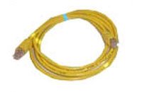
8.Networking Cables
* Category 5 cable is a twisted pair high signal integrity cable type often referred to as Cat5 or Cat-5. Most cables are unshielded, relying on the twisted pair design for noise rejection, and some are shielded. Category 5 has been superseded by the Category 5e specification structured cabling for computer networks such as Ethernet, and is also used to carry many other signals such as basic voice services, token ring, and ATM (at up to 155 Mbit/s, over short distances).
 CATEGORY 5 PATCH CABLE
*Category 5 cable includes twisted pairs in a single cable jacket. This use of balanced lines helps preserve a high signal-to-noise ratio despite interference from both external sources and other pairs (this latter form of interference is called crosstalk). It is most commonly used for 100 Mbit/s networks, such as 100BASE-TX Ethernet, although IEEE 802.3ab defines standards for 1000BASE-T – Gigabit Ethernet over category 5 cable. Cat 5 cables typically has three twists per inch of each twisted pair of 24 gauge (AWG) copper wires within the cables.
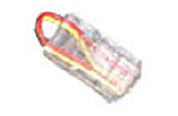
8P8C MODULAR PLUG

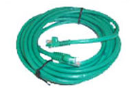
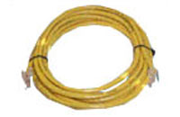
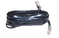
*A patch cable is an electrical or optical cable, used to connect one electronic or optical device to another for signal routing. Devices of different types (ie: a switch connected to a computer, or switch to router) are connected with patch cords. It is a very fast connection speed. Patch cords are usually produced in many different colors so as to be easily distinguishable.
> Cat5E cable Over molded Boots, Cat6 Patch cable Over molded Boots, Cat5F patch cable No boots, Flat Black satin RJ45 cable
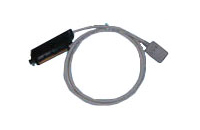
Cypress Industries is one of the few wire and cable manufacturers whose Asian manufacturing facilities have the ability to terminate 25 pair cables for Cat5 or Cat 3 applications. This allows us to provide extremely competitive pricing on higher volume 25 pair orders. We also have the ability to quickly manufacture these products in the United States to your specifications.
>25 pair to RJ45 cable,RJ45 loop back cable
*****
 audio Video cable
  computer cable
 networking cable
No comments:
Post a Comment